Understanding the Relay Node Concept in LTE
A few years back, the relay node concept was introduced in 3GPP release 10 to solve performance issues like the reduced data rate, the weaker signal and the higher interference encountered on the radio coverage edges of the macrocells of the basestations by expending the covered zone and increasing the capacities of the radio coverage both indoor and outdoor at a lower cost.
The Relay Node concept in itself isn’t new. At first, it was designed as simple radio repeaters that were receiving, amplifying the basestation’s signals and were diffusing them with all their noise and imperfections. But the LTE Relay Node (RN) is more than a simple repeater as it extracts the data from the received signal, applies the noise correction techniques and retransmits the new “clean” signal in its own coverage zone. So basically, instead of only repeating the signal, the relay node also increases the signal quality.
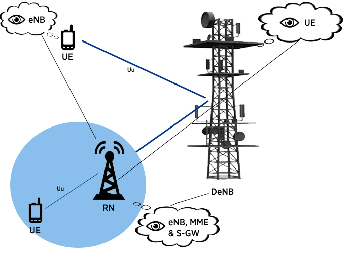
The Relay Node and the femtocell (or home basestation as defined in 3GPP’s release 9) are low-power (low coverage) basestations. The femtocell is mostly used for indoor coverage (residential or commercial), usually for use cases where one wants the coverage to be limited to the zone that is supposed to be covered, in order to avoid interference with the wireless communications happening in the surrounding areas. The particularity of the femtocell is that it is deployed without any coordination with the closest macro-cellular base station. That said, a wired connection to Internet is mandatory (optical fiber, DSL,…) to connect to the core network of the service provider. On the other end, the RN is connected to a macro eNodeB (basestation in LTE) called Donor eNodeB (DeNB) using a radio interface, which is a modified version of the Uu interface (usual interface between an eNodeB and the UE / cellphone).

Relay Node Concept
The DeNB not only shares its radio resources with the RN, but it also continues to deserve its own UEs. For a Donor eNB, the relay node appears as a UE, just as in return a RN sees the DeNB as an eNB, a Mobility Management Entity (MME) and a Signal Gateway (S-GW). By creating its own coverage zone, the RN appears as a eNB to the UEs. Consequently, the RN supports the functionalities of the eNB: it ends the protocols of the E-UTRA radio interface, the S1 (between eNB and MME) and X2 (between 2 eNBs) interfaces and a part of the UE functionalities like the physical layer, the 2nd layer and RRC that allows to connect wirelessly to a DeNB.
Depending on the way the wireless link to the core network is allocated, RNs can be classified as :
– In-band or type 1, if the backhaul link, which is the link between the DeNB and the RN, is allocated on the same carriers frequency as the access link (between the LTE RN and the UE). Since the links are time multiplexed in LTE-A, the reutilization of the carrier frequency is possible. Additional constraints at the backhaul link must be taken into consideration in order to avoid interference at the RN antennas.
– Out-band relaying case or type 1a, when the backhaul link operates on a different carriers frequency to that of the access link. One advantage of the out-band RN compared to the in-band RN is the relatively increased capacity of the backhaul link, thanks to the full-duplex feature. In fact the isolation between the backhaul and access links is literally achieved in the frequency domain, thus preventing further intercellular interference.
Although offering better performance, from the operator point of view, the separated carrier allocation at the RN access link might not be possible due to the lack of available spectrum or costly spectrum licensing and to the inefficiency in dedicating this frequency band only for relay-UEs. Fortunately, carrier aggregation (CA), another great feature of LTE-A, offers an attractive solution for relay type1a deployment. In carrier aggregation, a single carrier is used as the Primary Component Carrier (PCC) which is always active and is responsible for carrying out all the control procedures. Whereas the other carriers, known as Secondary Component Carriers (SCCs), are activated on demand to increase the UE’s performance. Additional Information about carrier aggregation can be found here. CA allows macro-attached users equipment (Macro-UEs) to have their maximum achievable capacity enhanced by enabling a SCC, while the Relay-UEs and the RNs use distinct components carriers as their primary carrier component.
In sum, LTE-A relay node, are designed to be low cost and lower power nodes which can be easily and quickly deployed when needed. They can be deployed in several scenarios: in rural areas to enhance the coverage, urban hotspot to enhance the capacity in order to cope with the high user density, group mobility to deserve users on public transportation, indoor hot spots to achieve high data throughput, etc.
 Skip to content