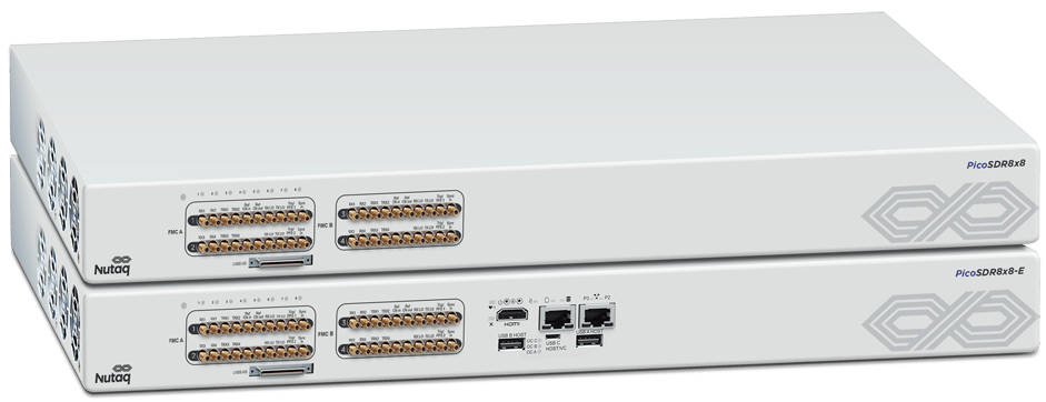
Key Features:
Phased-array, beam forming, direction finding and MU-MIMO is now affordable with this new 8×8 MIMO SDR, offering 8 TRx channels per FPGA. With the ability to connect two units for perfectly synchronized 16×16, automatic gain & phase calibration, dedicated links to bring all IQ streams into one master FPGA, building large MIMO systems has never been easier.
- 8×8 on one single FPGA
- Easy to connect two units for perfectly synchronized 16×16 or more
- Dedicated low-latency point-to-point links bring all IQ streams into one master FPGA (16×16 or more)
- Automatic gain and phase calibration for phased-array, beam forming, direction finding and MU-MIMO
- Fully integrated with Matlab Simulink and Xilinx System Generator (model-based design tools)
- AD9361 Radio Frequency Integrated Circuit (RFIC)
- Software defined up to 6 GHz and 56 MHz BW
- Small form factor: 385 mm x 360 mm x 45 mm
- Embedded Linux PC: connect remotely from any computer or run standalone
- Plug-and-play, with Ethernet, PCI Express and VITA-49 Radio Transport Protocol (VRT)
- Low Latency (75 µs roundtrip) and high speed (10 Gbps) PCIe interface
- QAM64 OFDM Ref Design*
*The reference design is currently available on the 1st PicoSDR Generation

8×8 on one single FPGA
Click on the image to enlarge it
70 MHz to 6 GHz on one single radio
The PicoSDR 8×8-E relies on one single 0-6 Ghz radio, built on the agile and high-performance AD9361 Radio Frequency Integrated Circuit (RFIC), that offers the full performance on all bands frequency.
- RF 2×2 transceiver with integrated 12-DACs and ADCs
- 70 MHz to 6 GHz frequency range with integrated fractional-N synthesizers (2.4 Hz maximum LO step size)
- Supports TDD and FDD operation
- Tunable channel bandwidth: 200 kHz to 56 MHz

- Receiver sensitivity with a typical noise figure of 7 dB from 200MHz to 4 GHz and 10dB from 70MHz to 6 GHz
- 100dB RX gain control with real-time monitor and control signals for manual gain
- Independent automatic gain control
- TX OP1dB : +18dBm from 200-4000MHz and +10dBm from 200-6000MHz
- Highly linear broadband transmitter (TM3.2 20MHz-16QAM LTE signal):
- ACPR: typically -45dB for +10dBm and 0 dBm at 2.4GHz and 5GHz respectively
- EVM: 2.5% and 3.5% typically for +10dBm and 0 dBm at 2.4GHz and 5GHz respectively
- TX noise: ≤−150 dBm/Hz noise floor
- 100dB+ TX gain control with 31dB external gain control
Rapid HIL Testing with no HDL Coding Necessary
Our fully integrated model-based design approach lets developers easily move through the model, simulation, code, hardware-in-the-loop, and real-time validation phases…iterating rapidly to refine their algorithms while benefiting from automatic HDL coding tools.
Hardware Ships Fully Debugged & Ready For Code
The PicoSDR ships with a software tool suite that contains all of the necessary IP cores, I/O interfaces, and stand alone APIs needed to enable immediate development of applications on the hardware.
Reduce Development Time By Up To 70%
Using a combination of our model-based design environment, GNU Radio, our QAM64 OFDM reference design, and auto-generated HDL code can shorten development cycles significantly.


